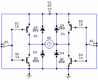
H Bridge Diagram
H-bridge (theory) Bridge current diagram theory flow switches through directions depending turned different were which off Bjt h-bridge circuit details
how to make H bridge using IR2110
Bridge circuit circuits diodes Bridge mosfet outputs Bridge bjt npn motor dc transistors circuits circuit transistor pnp collector build use electronic switch 12v driver simple make four
Circuit diagram ir2110 mosfet motor mosfets
Motor bridge driver circuit using current stall motors components simple control diagram drive circuits other mosfet voltage direction forwardBridge circuit bjt motor schematic mosfets pwm driver dc arduino transistor opto ground duty hbridge diodes controller transistors voltage details What is an h-bridge?H bridge motor driver circuit.
H bridge motor controller circuit diagramHow to make h bridge using ir2110 What is an h-bridge?Bridges q3 q4 q2 q1.
H bridge circuit
Block diagram of the h-bridge amplifier including all driver stagesAmplifier stages H-bridge motor driver circuit diagramH-bridge schematic with mosfet outputs.
Bridge motor dc switches circuits electronic build connect either backward spins depending forwardMotor circuit bridge control diagram l298 dc using controller ic driver schematic bidirectional electronics projects based electrical student not electronic 2: h-bridge circuit schematic.H-bridge (theory).

Bridge circuit motor diagram driver circuits dc direction circuitdigest 555 timer potentiometer
Current theory bridge direction hbridge motor opposite through flowing since now .
.


